 |
MD_Cubo LED Cube Arduino Library
2.1
Library to control LED Cubes
|
 |
MD_Cubo LED Cube Arduino Library
2.1
Library to control LED Cubes
|
This cube only requires a handful of discrete components a little bit of soldering to make the cube which fits on the breadboard.
See description here: https://github.com/MajicDesigns/MD_Cubo/issues/11
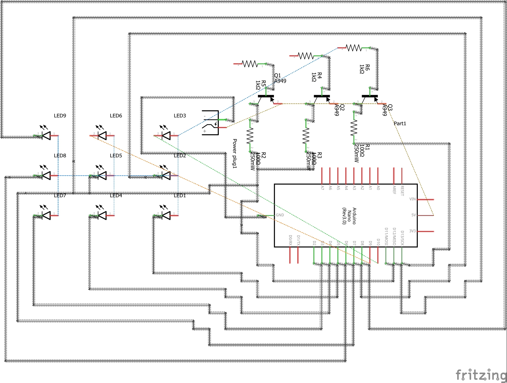
3 transistors (A949 PNP BJT's) are used to open each layer circuit to ground.
LEDs in the layer are numbered by column:
2  5  8
1  4  7
0  3  6
LED in each layer have a direct connection to Arduino digital I/O as follows:
LED  0   1   2   3   4   5   6   7   8
Pin  D4  D7  D10 D3  D6  D9  D2  D5  D8
The hardware architecture implemented shown in the schematic below.

Cube data is buffered in memory organized as vertical layers of 9 bits (1 word). At each refresh, the I/O for each LED in a layer (_LEDLayer) is set and the Arduino pin corresponding to that layer (_enableLayer) is set to ground (LOW) to enable the circuit for that layer.
The animate() call is used to scan the refresh of the cube. No interrupt timers are used in this implementation.
No intensity changes are implemented in this architecture.