 |
MD_Cubo LED Cube Arduino Library
2.1
Library to control LED Cubes
|
 |
MD_Cubo LED Cube Arduino Library
2.1
Library to control LED Cubes
|
Reference: jolliCube by jollifactory "JolliCube - an 8x8x8 LED Cube (SPI)" at http://www.instructables.com/id/JolliCube-an-8x8x8-LED-Cube-SPI/

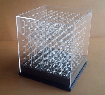
The monochrome jolliCube is implemented using 8 MD_MAX7219 ICs with an SPI interface to the Arduino controller, and is therefore a 'set and forget' type of device. The MAX7219 ICs are connected in series with the serial output of one device being the input to the next.
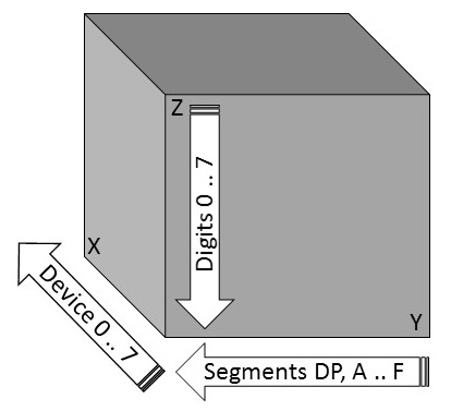
The hardware architecture implemented is shown in the figure below.

The software implements an SPI interface through the standard Arduino SPI object.
Cube data is buffered in memory organized as vertical layers of 64 bits (8 bytes) corresponding to the data for each 7219 IC, referenced to provide an origin point on the lower left corner of the cube. The cube data is held in memory buffers until an update() call is made, at which point it is entirely written to the cube through the SPI interface.
The intensity values 0..255 are remapped to 0..15 levels available in the MAX7219 IC (divide by 16).