|
MD_SN76489 Library
1.1
Library for SN76489 sound generator
|
|
MD_SN76489 Library
1.1
Library for SN76489 sound generator
|
The SN76489 Digital Complex Sound Generator (DCSG) is a TTL-compatible programmable sound generator chip from Texas Instruments. It provides:
The IC has 16 pins with the following pinout:
 D5 ->  1 +-----+ 16 <- Vcc
 D6 ->  2 | S N | 15 <- D4
 D7 ->  3 |  7  | 14 <- CLK
RDY ->  4 |  6  | 13 <- D3
/WE ->  5 |  4  | 12 <- D2
/CE ->  6 |  8  | 11 <- D1
AUD ->  7 |  9  | 10 <- D0
GND ->  8 +-----+ 9  <- N/C
| Signal | Description |
|---|---|
| D0-D7 | Command byte inputs |
| /WE | Active low Write Enable (latches data) |
| VCC | 5V |
| GND | Ground |
| AUD | Audio output (headphone jack) |
| CLK | 4MHz clock signal (see below) |
| /CE | Active low Chip Enable (connect to GND or MCU output if more than one IC shares D0-D7) |
| RDY | Ready signal (unused). |
Note: If multiple ICs are interfaced, then the ICs CE line must also be used to select the right device and share the data lines. This is not managed by the library and needs to be part of the user application.
The frequency of the square waves produced by the tone generators on each channel is derived from two factors:
Each channel's frequency is arrived at by dividing the external clock by 32 and then dividing the result by N. Thus the overall divider range is from 32 to 32768. This gives a frequency range at maximum input clock rate of 122Hz to 125kHz (a range from roughly A2, two octaves below middle A, to 5-6 times the generally accepted limits of human audio perception).
The clock signal may be supplied from external hardware or can be created by the MCU. This can be specified class initializer parameters.
The MCU may have a timer capable of generating the 4MHz clock. This is a hardware dependent function implemented in the private startClock() method. The output is usually restricted to a processor specific pin which can be connected to the IC CLK input. The currently supported hardware is
| CPU Type | Example Board | Resource | Pin |
|---|---|---|---|
| ATmega328P | Uno, Nano, Mini | Timer 2 | Pin 3 |
| ATmega32U4 | Teensy 2.0, Leonardo | Timer 1 | Pin 14 |
If the library does not have code for the particular MCU, a compiler warning is generated and the private startClock() method is compiled with no code. Obviously, this results in no clock signal generated by the MCU and an external clock signal must be provided.
If an external hardware clock is used, then the library can be prevented from starting the MCU clock in the class initialization parameters.
The derived class SN_SN76489_Direct uses 8 digital output data lines from the Arduino MCU and an additional Write Enable digital output to load the data into the SN76489 IC.
The data pins used are for the application to specify as part of the object initialization parameters. The D array parameter has pin numbers arranged to correspond to the IC pins (ie, pin D[0] is connected to IC pin D0, D[1] to D1, etc). The WE pin can be any arbitrary pin.
Connections between the MCU and SN76489 are mapped as shown below. The Arduino pins are arbitrary except the 4Mhz clock - the pins shown are used in the library examples.
| Arduino Pin | SN76489 |
|---|---|
| D0 [A0] | D0 [ 3] |
| D1 [A1] | D1 [ 2] |
| D2 [A2] | D2 [ 1] |
| D3 [A3] | D3 [15] |
| D4 [ 4] | D4 [13] |
| D5 [ 5] | D5 [12] |
| D6 [ 6] | D6 [11] |
| D7 [ 7] | D7 [10] |
| WE [ 8] | /WE [ 5] |
| 4Mhz [ 3] | CLK [14] |
| /OE [ 6] (GND) | |
| AUDIO [ 7] (Amplifier) |
The derived class SN_SN76489_SPI uses 3 SPI pins (LD, CLK and DAT) from the Arduino MCU to a 74595 Serial to Parallel buffer IC and an additional Write Enable digital output to load the data from the 595 outputs to into the SN76489 IC.
This uses less pins than a direct connection but requires an additional IC. The pins used are arbitrary and specified by the application as part of the object initialization parameters.
Connections between the MCU, 74595 and SN76489 are mapped as shown below. The Arduino pins are arbitrary except the 4Mhz clock - the pins shown are used in the library examples.
| Arduino Pin | 74595 buffer | SN76489 |
|---|---|---|
| D0 [15] | D0 [ 3] | |
| D1 [ 1] | D1 [ 2] | |
| D2 [ 2] | D2 [ 1] | |
| D3 [ 3] | D3 [15] | |
| D4 [ 4] | D4 [13] | |
| D5 [ 5] | D5 [12] | |
| D6 [ 6] | D6 [11] | |
| D7 [ 7] | D7 [10] | |
| Data [11] | DAT [14] | |
| Load [10] | LD [12] | |
| Clock [13] | CLK [11] | |
| /OE [13] (GND) | ||
| /MR [10] (+5V) | ||
| WE [ 8] | /WE [ 5] | |
| 4Mhz [ 3] | CLK [14] | |
| /OE [ 6] (GND) | ||
| AUDIO [ 7] (Amplifier) |
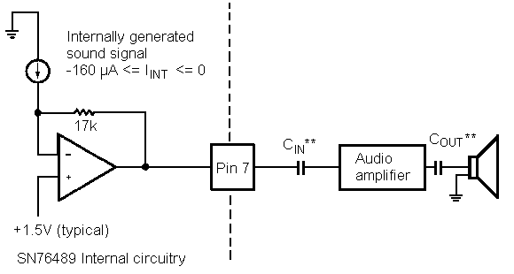
The Audio output from pin 7 of the IC is a mono signal that can be heard directly fed into earbuds. Connection to external speaker must be through an amplifier.
 1.8.16