 |
MD_TCS230 Color Sensor Arduino Library 1.2
Library to control TCS230 Color Sensor
|
 |
MD_TCS230 Color Sensor Arduino Library 1.2
Library to control TCS230 Color Sensor
|
This library supports the TCS230/TCS3200 color sensor and the more commonly available breakout modules available from many sources. The circuits for these modules are essentially identical except that the OE line may need to be modified (see below).
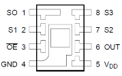
The TCS230 IC mounted in the breakout has the following pinout.
| Name | Pin | I/O | Description |
|---|---|---|---|
| GND | 4 | Power Supply Ground. All Voltages are referenced to this ground. | |
| Vdd | 5 | Supply Voltage (2.7-5.5V). | |
| /OE | 3 | I | Enable fo. OE high -> OUT becomes high. Multiple sensors can share the same OUT line. |
| OUT | 6 | O | Output frequency fo. |
| S0,S1 | 1,2 | I | Output frequency scale selection inputs. |
| S2,S3 | 7,8 | I | Photodiode (color filter) selection inputs. |
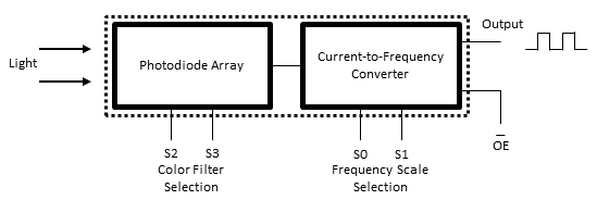
The operation of the hardware falls into two major functions, shown in the figure below. These different modules are controlled by setting the S0, S1, S2 and S3 pins. These settings are also shown in the tables below.
| S0 | S1 | Output Freq Scaling | S2 | S3 | Photodiode Selection | |
|---|---|---|---|---|---|---|
| L | L | Power Down | L | L | Red | |
| L | H | 2% | L | H | Blue | |
| H | L | 20% | H | L | Clear (no filter) | |
| H | H | 100% | H | H | Green |
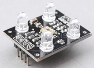
The sensor can be purchased mounted on any number of inexpensive breakout boards, similar in design to that shown above. These boards extend the package connections to header pins, and integrate LEDs for illumination of the target object.
Many of these boards include a design ‘feature’ connecting OE directly to GND. Test with a multimeter by measuring the resistance between OE and GND – zero ohms reading indicates a direct connection.
This configuration will create problems if
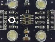
Restoring normal function to the OE input is possible by cutting a track on the PCB. This is found between resistors R5 and R8, highlighted by the circle in the figure below. This may be different for other boards, so it is wise to follow the connections to make sure the correct track is cut.
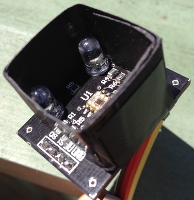
Another modification to make the device readings consistent and repeatable is to shroud the sensor. This can be made from black card, wrapped and taped to the breakout board. The shroud eliminates stray light and ensures all the reflected light goes back to the sensor - use black so that the light reflected back into the sensor does not include color components originating from the shroud. My setup is shown below.
