 |
MD_YM2413 Library 1.0
Library for Yahama YM2413 sound synthesizer
|
 |
MD_YM2413 Library 1.0
Library for Yahama YM2413 sound synthesizer
|

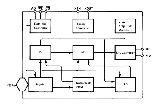
This is the block diagram of the YM2413. It has an 8 bit bus interface with one address line to select one of two write-only registers. One register is used to select the byte register to access 8 of the 271 internal register bits and one for writing data to the selected register.
On the analog side there are two outputs, one each for the Rhythm and Melody outputs.
The IC DIP package has 18 pins with the following pinout:
 GND ->  1 +-----+ 18 <- D1
  D2 ->  2 |  Y  | 17 <- D0
  D3 ->  3 |  M  | 16 <- Vcc
  D4 ->  4 |  2  | 15 <- RO
  D5 ->  5 |  4  | 14 <- MO
  D6 ->  6 |  1  | 13 <- /IC
  D7 ->  7 |  3  | 12 <- /CS
 XIN ->  8 |     | 11 <- /WE
XOUT ->  9 +-----+ 10 <- /AO
| Signal | Description |
|---|---|
| D0-D7 | Command byte inputs for OPLL command |
| /WE | Active low Write Enable (latches data) |
| /CS | Active low Chip Select (connect to GND or MCU output if more than one IC shares D0-D7) |
| /IC | Chip reset (pull up to Vcc or connect MCU reset) |
| AO | Address/Data discriminator |
| MO | Melody Output |
| RO | Rhythm Output |
| CLK | 4MHz clock signal |
| VCC | 5V |
| GND | Ground |
Note: If multiple ICs are interfaced, then the ICs CS line must also be used to select the right device and share the data lines.
| /CS | /WE | AO | Action |
|---|---|---|---|
| 1 | x | x | Chip not selected, inactive mode |
| 0 | 1 | x | Data bus inhibited mode |
| 0 | 0 | 0 | Address write mode |
| 0 | 0 | 1 | Data write mode |
The library uses 8 digital output data lines from the Arduino MCU and additional AO and WE digital outputs to load the data into the YM2413 IC.
The data pins used are for the application to specify as part of the object initialization parameters. The D array parameter has pin numbers arranged to correspond to the IC pins (ie, pin D[0] is connected to IC pin D0, D[1] to D1, etc). The AO and WE pins can be any arbitrary pins.
Connections between the MCU and YM2413 are mapped as shown below. The Arduino pins are arbitrary and those the pins shown are used in the library examples.
| Arduino Pin | YM2413 |
|---|---|
| D0 [D8] | D0 [17] |
| D1 [D9] | D1 [18] |
| D2 [D7] | D2 [ 2] |
| D3 [D6] | D3 [ 3] |
| D4 [A0] | D4 [ 4] |
| D5 [A1] | D5 [ 5] |
| D6 [A2] | D6 [ 6] |
| D7 [A3] | D7 [ 7] |
| AO [D4] | /AO [10] |
| WE [ 8] | /WE [ 5] |
| /CS [ 6] (GND) | |
| RO [15] (Amplifier) | |
| MO [14] (Amplifier) | |
| /IC [13] (MCU Reset) |
The Audio output from pins 14 and 15 (MO, RO) of the IC can combined into a mono signal to directly feed an amplifier and external speaker.